Welcome to the AIO Robotics ZEUS help page. Here you will be able to:
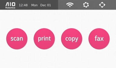
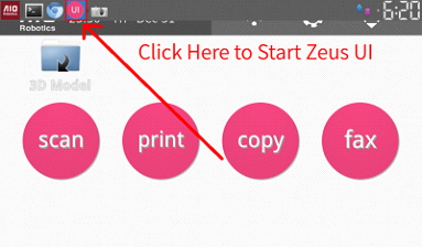
You can always return to the home screen pictured above by tapping the “AIO Robotics” sign at top left screen.
In this section user find all the needed information to start printing in 10 minutes.
Here is the link to our Quick Start Guide
Here is the link to adjust nozzle height , in case the nozzle is too close or too far from the glass turntable while printing.
Nozzle height adjustment is needed if the nozzle (extruder tip) is too close or too far from the turntable while printing.
The former causes the the extruder to print inaccurately.
The latter usually causes the extruder to interfere with the currently printed object.
Instructions
Follow these instructions to adjust the nozzle height:
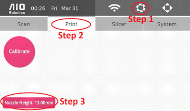
1. On the homepage, click on the gear image in the top right corner.
2. Click on the “Print” Tab
3. Click on Nozzle Height, which will display the following pop up message:

4. Adjust the nozzle height using the + (PLUS_ICON) and – (MINUS_ICON). The goal is to adjust the height such that there is only about 100microns or 2 sheets of paper in between the nozzle head and the turntable.
NOTE: If the nozzle is TOO CLOSE to the glass turntable, you will need to DECREASE the nozzle height. We suggest decreasing in increments of 0.4mm (for example, 12.8mm to 12.4mm). If the nozzle is actuallly scratching the turntable, we suggest decreasing the nozzle height by at least 0.8mm
5. Once satisfied with the adjustment, click save.
From left to right of the top panel:
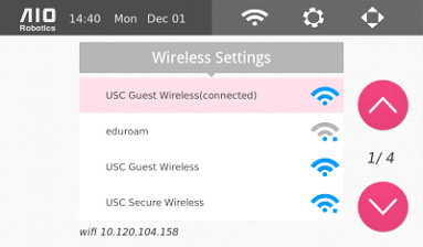
From the homepage, select the wireless icon to connect to to the internet via Wi-Fi. You many transfer files between ZEUS and a computer as well as update software in this manner. ZEUS may also connect to hidden wifi networks.
*The ZEUS can also be connected to the internet via ethernet, through the ethernet port located on the back of the device, next to the power switch.
From the homepage, select the Settings button (gear icon). You may change settings related to scanning, slicing, printing, & system settings. The four tabs correspond to those functions.
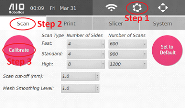
Scan Settings
Scanner calibration is recommended prior to operating ZEUS. Please ensure that the acrylic hood is shut during this process and that the device remains still. The process will take approximately 8 minutes to complete.
Note:
Scan Calibration
The calibrate button is used to calibrate the scanner.
Scan Parameter Setting
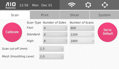
At the center of the page, there are three scan options
These options have corresponding numbers of sides and scan lines.
In the above figure we have the default values for each option.
Number of Sides - allows you to choose 1,2,4,8,16 equally spaced sides. Scanning 4 sides, for example, means the turntable will rotate 90 degrees & capture four sides (front, back, left, and right). The more sides the user selects, the more likely hidden crevices of the object can be scanned.
*Note for “scan side = 1”, ZEUS do not create a full printable watertight model, this is for quick preview purpose only.
The Number of Scans - corresponds to the number of scan lines in the object for each side. The higher number of scan lines, the slower the scan process but the quality of the scan will be better.
Set to Default - recover the original scan parameters. This includes the two options below, Scan cut-off and Mesh Smoothing Level. Also, when the options are changed, ZEUS will remember that change, even if the machine is turned off.
Scan cut-off - how much to cut off above the turntable. This is specified so that in case there is debris on the turntable or the calibration is not perfect, the system can ignore the noise. The default value is 1.5mm.
Mesh smoothing level - how much noise filtering is desired on the mesh reconstruction stage. 1.0 is the baseline. In general, higher smoothing level is better for simple objects with smooth surfaces (cylinder, square, rectangle). Low smoothing level is best for objects with complex or intricate surfaces (figurines).
Print Settings

This page has a print calibration and adjust nozzle button.
Slicer Settings
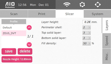
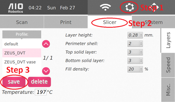
Setting up or changing slicer profile allows us to adjust print characteristics.
On the left side of the panel is the list of available profiles. The details of each profile will be displayed on the right side. Use the right vertical tabs to switch between different sub-groups of slicer parameters.
Underneath the profile list, there are the “save” and “delete” options to create and remove slicer profiles, respectively.
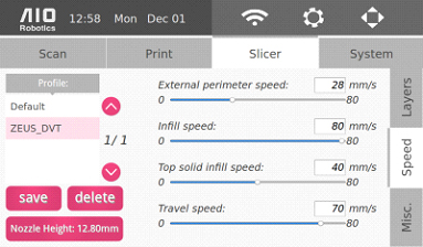
For the slicer parameters, changes for layers, speed, and miscellaneous options are enabled:
Layers
Speed
Misc
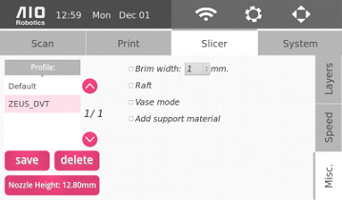
We plan to add more options for greater flexibility as development continues.
System Settings
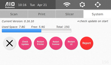
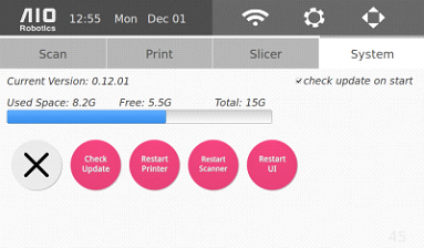
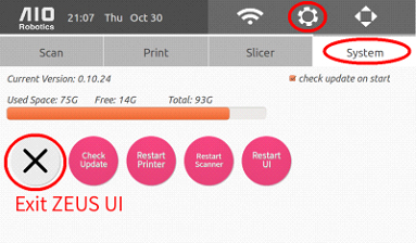
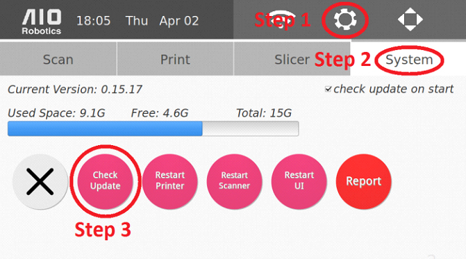
The system settings allow users to update and restart the software if needed.
Selecting the check update on start option on the top right will make the ZUES automatically update to the latest software each time the machine is switched on (when it is connected to wifi). In addition, one can also manually update the software by selecting the check update button.
Below the version number, a space progress bar displays the memory usage of Zeus. Zeus has approximately 15GB of total space. However, some of this space is used for the system itself. Depending on the content, pointcloud (.ply), mesh (.stl), and gcode files are on average, less than 10MB each. The AIO files can be larger due to the possibility of having multiple files within one AIO file.
Below the space progress bar, there are four other options to stop and restart parts of the system. The first, “X” button (cancel) closes the UI and takes you to the underlying Ubuntu operating system.
Below the space progress bar, there are four other options to stop and restart parts of the system. The first, “X” button (cancel) closes the UI and takes you to the underlying Ubuntu operating system.
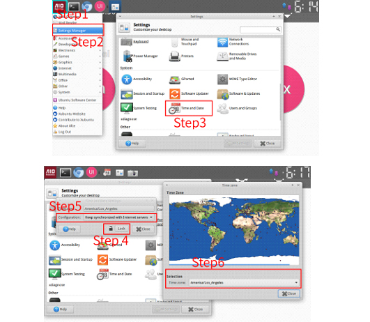
Advanced System Settings
Most of the advanced system settings are hidden in the Ubuntu operating system (OS). To reach these settings, we must first exit the ZEUS User Interface . To access many of these OS settings, a keyboard is necessary. However, the user can also enable a virtual keyboard.
The advanced settings are:
After performing the necessary changes, we can then „restart the ZEUS UI “:#restart_the_ZEUS_UI back up.
The control page controls the various ZEUS hardware modules. The are divided into three separate tabs as displayed: printer, extruder, and scanner.
In each tab, the current (in large pink font) and target (smaller grey) temperature of the extruder is displayed. The “light” button can be used to turn on/off the light inside the ZEUS.
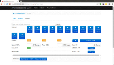
ZEUS hardware can also be controlled from a web control panel.
Printer
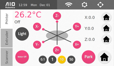
You can move the XYZ table using the movement buttons: X+, X- Y+, Y-, Z+, Z-. The movement can be done in increments of 0.1,1,10, or 50cm by selecting one of the increment buttons below the XYZ controller. You may also use the home buttons (the house icons) to center each individual axis, located on the right hand side. There is also a larger Home button which will center all axes with a single touch.
At the bottom right there is a Park button to park the extruder at the front of the turntable to make it more accessible.
The motor off button turns all the XYZ motors off.
Extruder
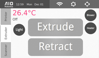
This page allows you to control all the functionalities related to the extruder. The extrude button grasps the filament and feeds it through the hole atop the extruder in through the nozzle. If you are having trouble making the filament line up to be fed between the two silver gears on the front of the extruder, then push down on the black hinge that is connected to the spring on the right hand side of the extruder.
The retract button performs the opposite function and pulls the remaining filament back up the extruder.
These two buttons can also be used to unclog the nozzle if the extruder becomes obstructed.
The blower button turns on and off the blower/fan on the extruder
The heater button heats up and turns off the nozzle.
Scanner
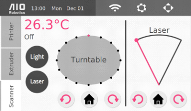
The scanner page controls the two scanning hardware modules: the turntable and the laser.
The turntable rotation control rotates the turntable clockwise or counter-clockwise. It will rotate the turntable by one sixteenth of a full rotation, or 22.5 degrees. The middle home button moves the turntable to the absolute home angle.
Another set of the same buttons controls the laser motor. The laser motor rotates the laser through the object for scanning. Each click of the rotation button in either direction moves the laser by 5 degrees. The range of rotation is 50 degrees and the home location for the laser is at the leftmost angle.
The laser button turns on and off the laser. It is best to turn the laser off when not in use in order to prolong its life.
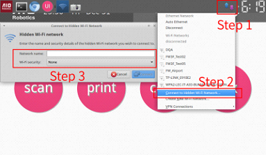
Below is the instruction to connect to a wireless network. Keep in mind that Zeus can also be connected via a wired ethernet connection at the back of the machine. (observe page FIXXX for input connector). In addition, it is also possible to connect to a hidden wifi access point.

To connect to a wireless network:
To connect to hidden wifi: FIXXX_KAI FIXXX_NUMBER_NOT_CORRESPONDING
1. Close the UI to go to the backend Ubuntu OS.
2. Plug in a USB keyboard on one of the front USB input.
3. Select the wireless settings on the top right menu. It will show a drop down
menu
4. Select „Connect to Hidden Wifi Network“, one of the options.
5. Enter the log-in credentials
Note: Please remember to close the lid of ZEUS during the calibration process to ensure that no outside light will affect the calibration.
Calibration Steps
1. Secure the calibration pattern on the turntable. Do this through either using a clear tape on 3 or 4 edges or glue so that the pattern does not shift during calibration. Also, make sure that the pattern is centered properly and perfectly hugs the turntable edges. If you desire, this can be done outside of the machine by taking out the turntable.
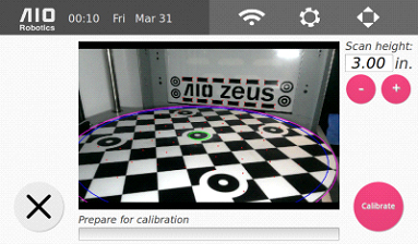
2. From the homepage, click on the gear icon, select the “Scan” tab, the press the round “Calibrate” button.
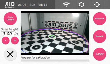
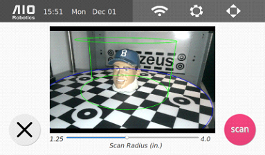
3. Select the desired scan height. The easiest way to select the right height is by placing the object within the green cylinder (scan radius). The factory default height is 3.0in (or 76.2mm). The maximum height is 4.4in (111.76mm). When selecting a height, make sure to leave some space at the top, preferably at least .2 inches on the screen. This is necessary so that part of the laser line falls on the background and can be detected in the image.
4. With the calibration mat over the turntable and properly placed in the machine, select the pink “Calibrate” button. Once calibration is successful, Zeus is ready to Scan.

For best scan results, you may scan with the calibration pattern in place.
Advanced Button Layout
The advanced calibration settings are not necessary and are only recommended if you have encountered a problem with the scanner, and suspect that calibration is an issue. In such a case, an advanced calibration may solve the problem.
To access the advanced calibration settings, press and hold the pink calibration button for a few seconds and release.
Here we have a number of calibration functions. The live image displaying the inside of Zeus with markers helps to determine whether the current calibration is sufficiently accurate.
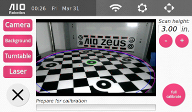
There are a few buttons, both on the left and the right side:
The Zeus comes, pre-calibrated and pre-tested for scanning, but if it was subjected to a large amount of movement then recalibration may be necessary.
Checking Calibration Alignment
The picture above shows how a perfectly aligned calibration would appear. Both the points on the background and turntable are displayed on the corner of the background pattern and turntable checkerboard pattern, respectively. In addition, the turntable center (small green radius) and outer (blue) circle also coincide with the turntable.
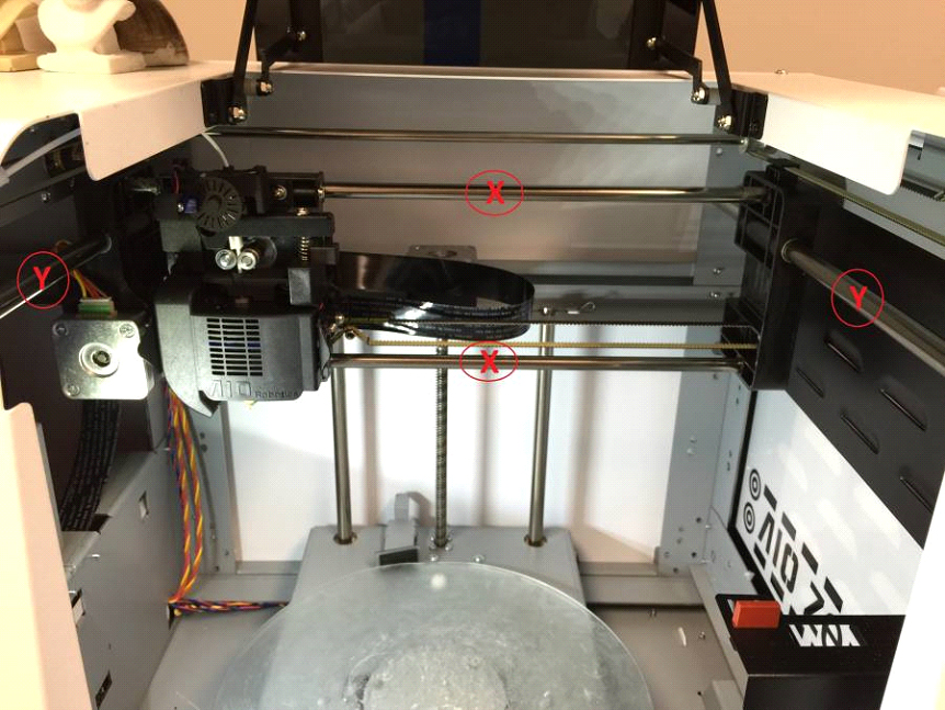
If round or square objects seem not to be printing accurately, the X, Y, & Z axis shafts may need to be lubricated. You will need teflon lubricant, and a brush. Apply teflon lubricant to the two x-axis shafts, the single z-axis, and the two y-axis shafts pictured below.
To calibrate the printer, you will need a vernier caliper, & a marker or pen.
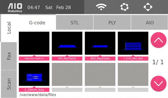
first click “Print,” then the “STL” tab, and locate and print two pre-loaded files “1_0.35_thin_wall” and “2_20mm_box”
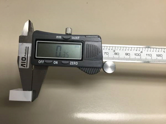
Thin Wall Test
Once the thin wall is printed, remove it from the printer and measure the thickness of any side of the wall with a caliper. The reading should be 0.35 (±.03 error margin). Write down the reading from the caliper measurement.
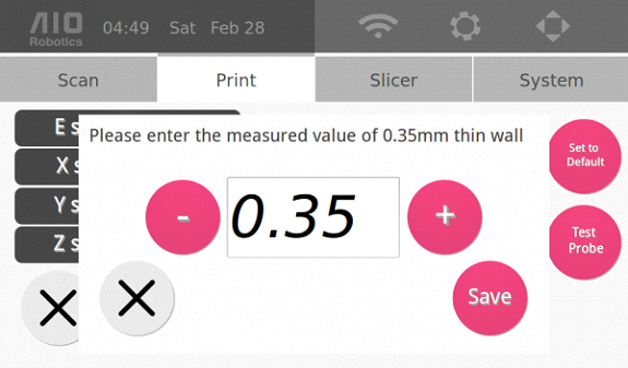
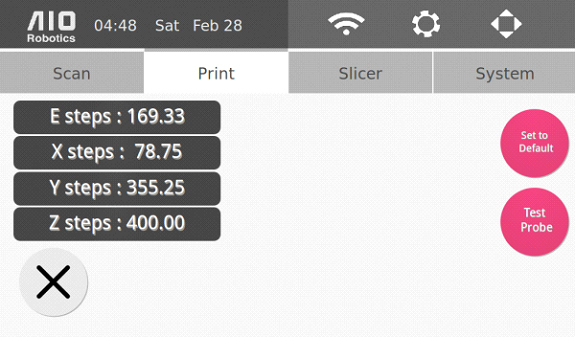
Go to the settings page through the “gear” icon on the top right of the homepage, and click the “Print” tab. Press the “Calibrate” button to display the following page:

Click on “E steps” and enter the reading you received from the thin wall caliper measurement when the following page appears. Click on “Save.”
Box Test
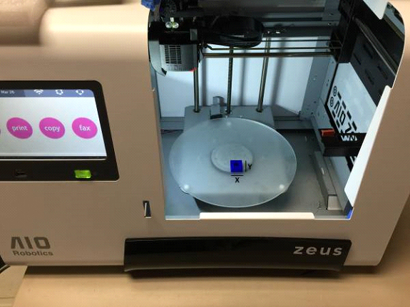
Once the “2_20mm_box” file is printed, label the box with x & y labels. This is crucial for measurement.
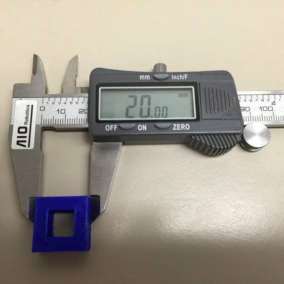
After labeling, remove the object from the printer and measure it, the reading for both x and y axis measurements should be 20.00 (±.03 error margin). Write down the reading from the caliper measurement.
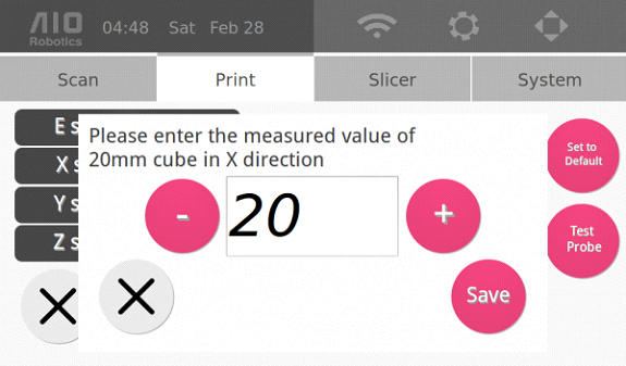
Go to the settings page through the “gear” icon on the top right of the homepage, and click the “Print” tab. Press the “Calibrate” button to display the following page:
Click on “X steps” to enter the reading you received from the x-axis measurements when the following page appears. Click on “Save.”
Then, click on “Y steps” to enter the reading you received from the y-axis measurements when the following page appears. Click on “Save.” Now your printer is fully calibrated.
Nozzle height adjustment is needed if the nozzle (extruder tip) is too close or too far from the turntable while printing.
The former causes the the extruder to print inaccurately.
The latter usually causes the extruder to interfere with the currently printed object.
Instructions

Follow these instructions to adjust the nozzle height:
1. On the homepage, click on the gear image in the top right corner.
2. Click on the “Print” Tab
3. Click on Nozzle Height, which will display the following pop up message:
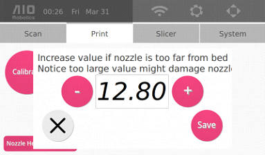
4. Adjust the nozzle height using the + (PLUS_ICON) and – (MINUS_ICON). The goal is to adjust the height such that there is only about 100microns or 2 sheets of paper in between the nozzle head and the turntable.
NOTE: If the nozzle is TOO CLOSE to the glass turntable, you will need to DECREASE the nozzle height. We suggest decreasing in increments of 0.4mm (for example, 12.8mm to 12.4mm). If the nozzle is actuallly scratching the turntable, we suggest decreasing the nozzle height by at least 0.8mm
5. Once satisfied with the adjustment, click save.
As an example, let’s create a slicer profile to print a hollow object instead of solid. That is, we are going to setup a print profile that does not have infill:
Let's give this new profile a try:
Slicer Config File for Slic3r
If you want to create a gcode from your own computer, you may use the following slicer setting for Slic3r
Current Supported Slic3r version is 1.2.0
Instruction:
Instruction:
Instruction:
Open a browser and go to http:(ZEUS IP Address):8080 (for example :http://127.0.0.1:8080) The IP address can be obtained from the bottom of the wifi screen.
How to unclog the extruder
Once you see filament extrude smoothly out of the nozzle tip, go back to the temperature setting and reduce the temperature back to 197C. The Zeus should be ready to print once again.
Below is the pertinent information about scanning:
3D scanning is the process of capturing the surface (and sometimes also the inner parts) of an object and storing it into a digital file. Once the information is digitized, the user can perform many tasks, such as editing, printing, etc.
Generally, there are two methods to perform scanning. The first technique is contact based. This technique requires physical measurement through various processes such as utilizing a gantry system. This is quite time consuming, and requires much attention to detail. The other type of scanning is non-contact. This can come from acoustic, magnetic (MRI), or optical measurements. Our method is of this variety.
Our technique utilizes a camera that takes pictures of the scanned object while being projected upon by a rotating laser. This system also makes use of a turntable that rotates the object to scan its back and side portions. The combined laser points on the surface of the object is called a point cloud and is stored as a file with the extension “.ply”.
However, there are also instances in which simply rotating the object is not sufficient. For example, to acquire an accurate scan of the top of an object or the inside part of it (i.e. a mug) requires the object to be laid on its side. We are currently implementing a multi-scan function in which multiple scanned poses can be registered together to achieve a more complete point cloud.
Our system is fully automated from the point-cloud acquisition step (generating the .ply file from scanning) through the printing step. To do this, ZEUS processes the point cloud (.ply) to construct a 3d surface mesh (.stl) and then slices the object (gcode). For printing purposes, it is important that the resulting mesh is a watertight manifold.
The scan process is complete at this point, however, for a copy, the system will then proceed to slice the watertight mesh to create a what is called a gcode file, which is then ready to print on the turntable. The print process is described in greater detail in the print section. The copying instructions can be found in the scan and copy sub-sections. For the fax function, please see the fax section.
Size Requirements
The maximum scan size is:
For the best quality scans, the object should be larger than:
We believe the optimal scan size can still be decreased in the future as we continually improve our scan algorithm.
Automatic Software Updates - For instructions to update the software or turn on automatic updates after each power up, go to this page.
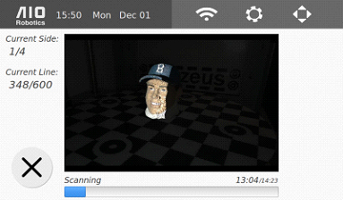
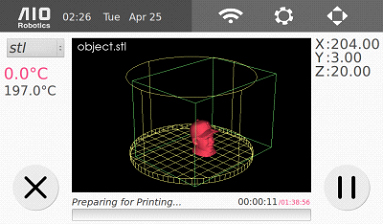
Below is the scan preview page that displays the scanning area in the fifth step of the scanning process.
Weight
Object should not weigh than 4.4lb or 2kg, because the object may tip the turntable.
Form
Objects should have a sturdy base that will not move during the scan process while the turntable rotates. If the object has a round base for instance, applying clay on the base may help stabilize the object.
Ready-to-Scan Objects
Opaque, matte, light-colored objects are ready to scan because their surfaces do not absorb, deflect, or adversely affect the laser light.
Objects Requiring Scan Preperation
Transparent, translucent, shiny/reflective, fuzzy, and very dark objects may need preparation before they are ready to be scanned.
The surface may need coating such as baby powder or washable tempera paint.
Below we show the different objects before and after treatments, and the resulting scan and copy. Where to buy powder: FIXXX
Dark plastic objects:
DORAEMON FIG_VERY_DARK_OBJECT_ORG
FIG_VERY_DARK_OBJECT_POWDERED
FIG_VERY_DARK_OBJECT_POINTCLOUD FIG_VERY_DARK_OBJECT_MESH
FIG_VERY_DARK_OBJECT_COPY
The dark color of the object (jacket and hat) absorbs the laser so much that it is not detectable by the camera.
The same should also be done with shiny ceramic, because the change is color changes the surface geometry.
DUTCH BOOT CERAMIC FIG_VERY_DARK_OBJECT_ORG
FIG_VERY_DARK_OBJECT_POWDERED
FIG_VERY_DARK_OBJECT_POINTCLOUD FIG_VERY_DARK_OBJECT_MESH
FIG_VERY_DARK_OBJECT_COPY
For Translucent plastic/wax (particularly white colored wax such as candles) and transparent glass must use painted on to prevent the light from penetrating the surface. glass: thicker powder or tempera paint: the point is to not allow light to shine through
FIG_TRANSLUCENT_OBJECT_ORG
FIG_TRANSLUCENT_OBJECT_POWDERED
FIG_TRANSLUCENT_OBJECT_POINTCLOUD
FIG_TRANSLUCENT_OBJECT_MESH FIG_TRANSLUCENT_OBJECT_COPY
FIG_TRANSPARENT_OBJECT_ORG
FIG_TRANSPARENT_OBJECT_POWDERED
FIG_TRANSPARENT_OBJECT_POINTCLOUD
FIG_TRANSPARENT_OBJECT_MESH
FIG_TRANSPARENT_OBJECT_COPY
Below we detailed the powdering and painting process.
Painting Process
First of all make sure that the object that you are painting would not be damaged by liquid. That is, if the object has electronics inside, be extra careful in applying the paint as well as removing it.
Second, make sure you use a washable tempera paint such as washable crayola paint. Use light color such as white or yellow.
When applying the paint, start with a thin coating first and check whether
the object surface is sufficiently covered throughout. If light can still go
through the object in the case of a glass object, add another thin layer. Make
sure there is no clumping that may alter the surface geometry or deteriorate the
desired scanned details.
FIGURE_GOOD_THIN_COAT
FIGURE_THICK_CLUMPY_COAT
Below is a video to scan and copy an object using Zeus.
1. Select the “AIO Robotics” logo to get to the home
screen
2. Select Scan.
3. The following page will appear:
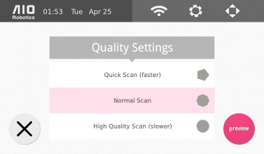
Select Scan Setting: Quick – 10–15 minutes Standard – 16–25 minutes High – 25–35 minutes
There is a trade-off between scan time and scan quality/detail desired. *Each of these options has corresponding scan lines and number of sides. Refer to scan settings section for definitions and how to change them.
4. Select “preview” to proceed. The following scan preview page will appear.

5. Using the camera image, place and center the object within the scanning area, represented by the green cylinder. Select here to see how to adjust the scanning area.
6. Select scan to start the scan. Please keep the acrylic hood shut during this process.
7. Wait for the scanner to finish. As the scanner is moving: the display show the progress. If needed, press cancel to stop scanning. Note that the scan results up to the cancellation time are saved to scan/DATE_TIME.aio file (current date and time, for example, 2014_10_12__10_00_00.aio).
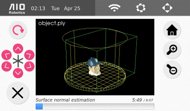
8. After the scanning phase is finished, Zeus will proceed to mesh the point cloud.
9. When the mesh is complete, ZEUS will display it, and save it to scan/DATE_TIME.aio by default. User can select the “save as” button to change the name as desired.
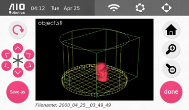
10. Select “done” to go back to the front page.
Software updates are released by the AIO team to improve or add new functions and features based on our customers needs, wants, and feedback.
To ensure that the ZEUS system is running smoothly, please be sure to update the system software of your ZEUS regularly. You can have ZEUS automatically check for system updates whenever it boots up and is connected to the internet by checking the box below.
Here are the steps to perform a software update
Below is a video to show you how to scan and copy an object using Zeus.
1. Go to the home page by selecting the AIO logo in the top left corner.
2. Select Copy.
3.-8. The next set of instructions will be identical with steps 3 – 8 in
the scan instruction section.** Then, please continue with the instructions
below.
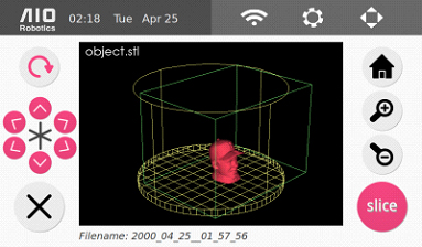
9. ZEUS will display the resulting .stl file at the end of meshing. To
continue, select “slice”.
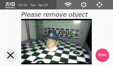
10. The page below will be displayed. Remove the object from the turntable. At this point, make sure to remove the calibration mat if it is still on the turntable.
11. Select “print” to go to the slicer page.
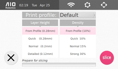
This page allows you to select the desired slicer profile (here it is set to the “Default” profile), as well as layer height and density. The latter two options override the parameters that are set in the selected slicer profile. To change or learn about the parameters of the slicer profile in more details, go to the slicer settings section.
12. Select “slice” to slice the object. At the end of the slice, the print preview page will display the resulting gcode.
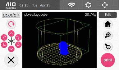
13. Select “print” to begin printing. There is a progress bar at the bottom of the screen, as shown below, that will tell you how much of the print is done and will tell you approximately how much longer the print will take. Wait until the print is finished before removing the printout.
This video takes us through the fax process.
VIDEO_FAX
You can either fax from a scanned object, or from a stored model, which can also be a previously scanned object.
FIG_FAX_FROM_SCAN_OR_STORED_MODEL
To fax an object that has not yet been scanned:
1. Go to the home page by selecting the AIO logo in the top left corner
2. Select “Fax”, you will see the following page:
FIG_FAX_OPTION
3. Select “scan” for faxing the 3D model of object that you put in the turntable.
4. – 9. The next set of instructions will be identical with steps 3 – 8 in the scan instruction section . We then continue with the instructions below.
10. ZEUS will then display the resulting mesh file at the end of meshing. Then, select “fax”.
FIG_MESH_DONE_FAX_BUTTON
11. Afterwards, select “slice” to slice the object. We can also select the desired slicer profile. This will be described in more details in the print section.
FIG_SLICE_should_be_available.
12. Select “fax” on the following page.
FIG_PRINT_PREVIEW
13. In the “fax send” page, displayed below, select your recipient before selecting “send.”
FIG_SEND_FAX
Scanning Troubleshooting
Note: Increasing the resolution quality of the print will also increase the print time.
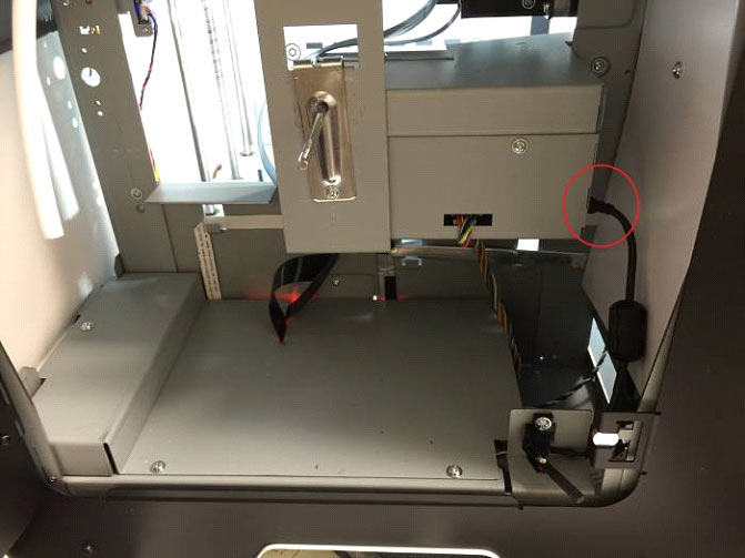
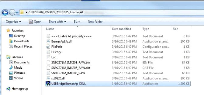
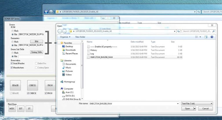
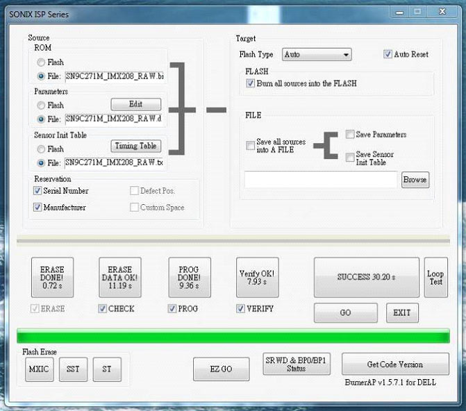
If you've encountered a camera firmware issue. The following steps should solve the problem.
These are the things you'll need: